• Hello Guest, welcome to the initial stages of our new platform!
    You can find some additional information about where we are in the process of migrating the board and setting up our new software here

    Thank you for being a part of our community!

stator volts and other electrical maddness

1968 volvo

Well-known member
Joined
Apr 29, 2021
Location
Santa Rosa California
Got my alternator tested today and it passed on everything accept for stator volts. Is that a thing or am I just confused. will the alternator work like that? Also I got a new voltage regulator to replace the part that was in it. because the old voltage regulator wasn't the correct part some of the wires don't match up. I got this regulator. https://www.rockauto.com/en/catalog/volvo,1968,142,1.8l+l4,1286670,electrical,voltage+regulator,4884 Note I didn't get it form rock auto but same idea for part. What wires need to go to the regulator. the old set up had a ground wire going to the mounting piece on the regulator, a wire coming from the male connector on the back of the alternator, and a black wire coming from the uppermost terminal of the alternator. However sketchy this system sounds, it did work for a while so I don't think that the wiring being fricked is the only problem. Also the colors of the wires cant be trusted as the guy before me didn't care about any later mechanics. :lol:
 
I'm not familiar with the 140 series and what they'd likely have today for an alternator/regulator. If you can find the 1976+ TP11402 electrical greenbook (try ozvolvo.org/archive/), it covers a slightly more recent Bosch 240 alternator with an external 3-wire regulator, which may be close enough for your '68.

In general, the 3 wires to the external regulator go to tabs on the back of the alternator for: ground/D- (probably a black wire), DF (maybe green or white wire), D+ (probably red wire). If you can post a picture of the back of your alternator, that would help.
 
Sounds like your alternator has failed. AFAIK the stator produces the juice, in AC, and the diodes convert it to DC.
Suggest you try and install the appropriate, correct alternator for your vehicle, rather than cobbling together other parts. Also suggest you get one of these, they’re invaluable , color coded and very easy to read.

https://colorwiringdiagrams.com/products/volvo-142-144-145s-1967-1968-1969-1970

Good luck.
 
Thanks guys. I may try to see if there is a gm single wire conversion that I can put into the alternator housing. Same footprint, but more amps options and just one wire going to the positive of the battery. nothing else. A mechanic friend of mine said that I might be able to find a conversion at a local shop. I don't know but I'll see what is available. He doesn't know much about Volvos but he's smart so I'm going to consider it. Thoughts?
I don't understand electrical very much and I'm not interested in learning about it right now, I just want to finish up this so that I can drive it again and one wire with no other complications seems to be a good way to that end.
 
Single wire conversions do not fit into the 'alternator housing'. Single wire conversions mean a complete replacement of the existing alternator with a new single wire alternator. You can get the full details on single wire installs here:

https://www.sw-em.com/altkit.htm

The biggest problem is finding an alternator with the correct pulley offset so that it lines up with the water pump pulley. I have seen some installations that machine the lower pivot to move the alternator backwards / forwards to get alignment. That weakens the lower pivot leading to potential problems. The SW-EM adapter fixes the alignment problem.
 
check this out

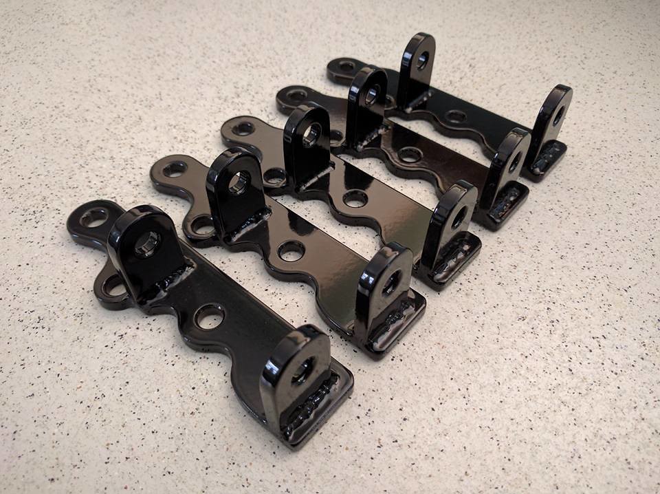
I make these for the 80 or 100 A Denso unit from 240's. They work great.

23948568528_d4c04c3cce_b.jpg


23948568618_0e022a282a_b.jpg
 
That lower bracket was discontinued on the block for the 140 engines. They just use one large bolt through the lower hole in the alternator into one threaded hole in the block. It's also how my 123GT was setup.
 
That lower bracket was discontinued on the block for the 140 engines. They just use one large bolt through the lower hole in the alternator into one threaded hole in the block. It's also how my 123GT was setup.

Correct for the later alternator equipped engines. I think the very first year of the 140 still had the B18 and they were generator equipped and I believe still had the lower bracket. The later engines have the hole for the alternator pivot bolt; but, still have the 3 holes for the bracket so you can use the alternator brackets with the later B20 block. The only thing to be aware of is because of the pulley offsets and alternator pivot dimensions, Canuck's and the SW Em brackets are alternator specific. Other alternators may work; but, you are on your own in terms of fit.
 
Last edited:
That lower bracket was discontinued on the block for the 140 engines. They just use one large bolt through the lower hole in the alternator into one threaded hole in the block. It's also how my 123GT was setup.

:nod:

Remember to retighten the pivot bolt after adjusting the belt tension or it will fall out.
 
Since you already have the replacement voltage regulator, I'd just wire it up correctly and see if it all works OK. You can buy a cheap cigarette lighter voltage gauge and usb jack off of ebay to keep an eye on the battery voltage while driving. You can also find lots of old threads here on 140 alternator conversions (google: "140 alternator conversion site:turbobricks.com").

When you originally said:
Got my alternator tested today and it passed on everything accept for stator volts.
Did they provide a printout, or any more details on what your alternator measured versus the pass/fail voltages?
 
Can the OP post photos of what he's dealing with? That may make it easier for others.

Like how the existing alt. is mounted and what brand/model it is?
And is the voltage regulator that is referenced from the rockauto site the actual regulator that he's using?

Maybe this info was in another thread?

https://forums.turbobricks.com/showpost.php?p=6239429&postcount=30

https://imgur.com/a/bBICEpL some pics of the engine.
Is the area in question look like what is required for ps.
Also I didn't tap the hole as the photo may suggest. there was already threads i just cleaned them with the tap.
also the little green box near my passenger side headlights what is that?
 
Since you already have the replacement voltage regulator, I'd just wire it up correctly and see if it all works OK. You can buy a cheap cigarette lighter voltage gauge and usb jack off of ebay to keep an eye on the battery voltage while driving. You can also find lots of old threads here on 140 alternator conversions (google: "140 alternator conversion site:turbobricks.com").

When you originally said:

Did they provide a printout, or any more details on what your alternator measured versus the pass/fail voltages?

No the auto shop I went to didn't seem very competent. I would have chosen somewhere else but I couldn't think of any and all the other places I had gone to earlier didn't even try to test it. I will update you guys with some better photos tomorrow or Monday. Would have done it sooner but I was lazy and busy.
 
Back
Top