• Hello Guest, welcome to the initial stages of our new platform!
    You can find some additional information about where we are in the process of migrating the board and setting up our new software here

    Thank you for being a part of our community!

Tach output on MS 3.57 MSII

thelostartof

unbalanced chemical
300+ Club
Joined
Jun 26, 2002
Location
Apache Junction, AZ
I am trying to figure out which wire is my tach output for the box so I can get my dash and stock tach working.

I have tried the Brown Spark A wire and I get nothing, I am wondering if anyone else has some quick tips to figure this out.

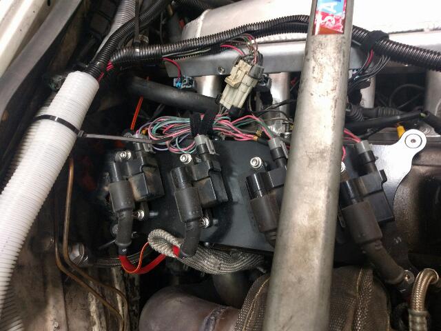
I am running Truck coils.

The only unused wires I have on my harness that I can see are 3 of the 4 spare outputs (tan wires) and then the brown spark A wire.

Thanks.
 
I don't recall the 3.57 board having an integrated tach output. The IAC driver outputs have a 12v biased output, but it's been so long since I've dealt with MS2 that I'm not certain IAC1 or IAC2 are valid options for tach output in software.

Any other output from the 3.57 board is a low side switch and you'd need to come up with an external circuit to drive the tach. A gutted relay is the most popular option.
 
Any other output from the 3.57 board is a low side switch and you'd need to come up with an external circuit to drive the tach. A gutted relay is the most popular option.
Toyota Tacho Negative Coil - Copy.png

tach-boost-02.jpg

And just use one of the spares output to drive it: consult the Megamanual
attach to the pink and white wire on cluster (1993 940, may be a different color depending on year)
20140731_145723.jpg
20140731_145730.jpg
 
There are a bunch of different CPU outputs that can supply a tach signal. If you have the IAC1 or IAC2 output available, they'll drive 0volts to 12volts. This may be enough for your tach. If available, you can temporarily wire MS to tach and use the MS Testmodes/OutputTestModeI/O menu, with ignition on but engine not running, to generate a test signal.

Most folks need to add a gutted relay coil to generate enough voltage for the tach to trigger. This can use most any MS output, but needs a transistor and a resistor, or two, in addition to the relay coil.
http://turbobricks.com/forums/showthread.php?t=311116

You'll also need to check inside your MS box to see what CPU signals have been jumpered to your spare wires.
 
Good to know it was not me.

So I have read about this gutted relay before, and looking at it I see some pictures that help, I will pull one apart tonight if I can find time and see if it makes sense what I need to take apart in it. Does anyone have a little better picture of description on what I take apart in it?

Thanks.
 
Find the part that moves and remove it. Otherwise, your relay will buzz annoyingly as rpm goes up and down. If there's a wire/woven cable connected to the moving part, just clip it off flush.
 
ok so I build the above listed circut and all I get is a constant .7V outut for the tach. When i connect it I see the tach jump to maybe 100 and the back to zero and then again i tried and it goes to 88 and then back to zero (using a digial tach that was piggybacked on the stock volvo tach).


Idea's? Did I maybe do something wrong?
 
Check that:
- tacho output is setup in tuner studio for correct MS CPU pin
- MS CPU pin is jumpered inside MS box to correct pin on DB-37
- At idle, see if you see a signal on the tacho wire from the MS box.
It should be 0 to 5volts, or 0 to 12volts, at engine speed.
[you can also use the tuner studio Testmodes I/O pins section to generate
a tacho output without the engine running]
- disconnect wire from gutted relay to dashboard tach. Is measured signal still 0.7v?
- disconnect +12v from the gutted relay too. Is measured signal still 0.7v?
- re-check wiring of transistor, resistor, relay coil, etc.
- maybe your piggybacked digital tach is causing too much load, can you try without it?
 
Pages 41 - 42 of the MSExtra hardware manual describes the circuit for driving a tach that needs a significant voltage spike. Same circuit as described by Turbomatic. Different relay coils will give different results.

How did you determine that you are getting a constant 0.7 volt output? Did you use an oscilloscope to make the measurement? If you use a digital voltmeter you are not going to get an accurate indication of the signal. If the digital tach is the type designed to take a signal off of a conventional coil - terminal, it should work with the circuit. Double check your wiring. Make sure you have transistor connected correctly. If you are using the IAC for your tach output, remember to connect up the 12v supply jumper.
 
I did not have a ton of time to mess with this this weekend but some quick basic updates.

I tested my LH 2.4 car and with my DVOM i am able to see the 12v-0v-12v-0-etc movement so because of this I would expect that if I can get the same kind of readings on the same meter then I can confirm that MS is correctly outputting the signal to my tach . . .no?

So another quick test hooked up to the br MS-Spark-A wire which I have confirmed going to pin #36 on the DB37 and with everything hooked up I am just getting a constant 13.7V(battery) out of the signal wire coming out of this setup. I have used another non gutted relay and I get no clicking of this relay.

I will trying to find some time this afternoon to do each of those tests today bobxyz. Otherwise I have rewired another circuit and had someone else double check it, I have tried this on the Fidle along with JS10 (IGN) and i get the same results of a running battery voltage signal for the tach out. If it disconnect the 12V power to the relay then it goes back to zero.


I am starting to think the way the MS box was setup to run the Truck coils off the main DB37 that something might be causing this issue. I am going to shoot another message to the guy who set it up to see if he has any other idea's.

What 12V needs to be setup for using the IAC (I am guessing you mean Fidle) or do you mean IAC1?

I have been doing some reading of other threads and a few points people mention to check to see if certain things are jumper-ed and mine seem to be correct for those few points they mentioned.

Either way I am going to pull apart my box again today and get a few pictures of the insides so I do not have to keep pulling it apart to check things.

Thanks.
 
You talk about running 'truck coils' - plural. That is a little non descriptive. Do you mean GM coil near plug truck coils and that you are running individual coils on each plug?

If you are using the GM coil near plug coils they are likely logic level coils (each coil has 4 or 5 connectors on the plug). If that is the case and pin 36 is coil A, you should be measuring a transition between 5 volts and close to 0 volts. You should not be getting battery voltage on pin 36 if you are set up to run logic coils. Or do you have some different set-up running a non logic level coil with high current drivers in the MS? That would give you battery voltage on pin 36 if the engine is not running and the drivers are set to switch the coil negative terminal.

If you want to use IAC1A or !AC2A to drive the circuit for a tach output, you have to insure that the jumper from s12 to js9 is in place, otherwise the transistor in the tach circuit will not get any voltage in its base circuit and nothing will happen (if you are using one your idle air stepper motor will also not work without this jumper).
 
The battery voltage I am getting out of the dummy relay and transistor setup that was posted above. Out of Pin #36 I am getting nothing at all.

I am pretty sure that the spare outputs on this setup are being used to drive my coils so I can not use IAC1/2, I will double check later today.

When I say truck coils I mean the COP setup off a GM, the wiring is a mess as I am waiting for my wire loom to come in this week and then I will clean it all up.
rps20160125_160318_537.jpg
 
I am not a GM coil expert; but, those look like logic level coils.

You will get a constant 12 v out of your tach driver circuit if the transistor is not getting any signal on its base. What pin on the MS do you have the base of the transistor connected to and is that port software configured to provide a tach signal? MSII does not come with a dedicated tach output. If you want a tach signal you need to software configure a spare port to provide the tach signal. If you don't have any spare ports, I think you are screwed in terms of trying to use the Volvo tach. You will have to use an aftermarket tach which supports a logic level input and drive it off one of th ecoils.
 
MS doesn't drive the coils off of the IAC driver, so unless you have other outputs occupied by IAC1/IAC2 then they should be available to use.

No circuits needed to drive the relay coil off of the IAC1/2 outputs, they are already set up to drive low current inductive loads.

As already mentioned, S12C needs to be jumpered to JS9 in order for the stepper driver to work properly.

Like I said this MS box was mod'd so that the outputs were changed around, When I bought the box the coils were being run off the separate DB15 on the other side and it was re-wired up with another board internally to run the coils off the DB37 and I think the outputs uses happen to of been those, I will get pictures tomorrow as I didn't get around to doing anything on the inside of the car tonight like I wanted to, But I will get some pictures and more input. S12C is Jumpered to JS9 IIRC as I already checked that.


I am not a GM coil expert; but, those look like logic level coils.

You will get a constant 12 v out of your tach driver circuit if the transistor is not getting any signal on its base. What pin on the MS do you have the base of the transistor connected to and is that port software configured to provide a tach signal? MSII does not come with a dedicated tach output. If you want a tach signal you need to software configure a spare port to provide the tach signal. If you don't have any spare ports, I think you are screwed in terms of trying to use the Volvo tach. You will have to use an aftermarket tach which supports a logic level input and drive it off one of th ecoils.

On the Base I was connecting that to the Br wire on Pin #36 on the DB37. So it makes sense that something is not hooked up hence why I am not getting an output on that line. in Tunerstudio is was set to the default JS10 (ign) as that should be the ign output right which is pin #36?

I do have 3 of the 4 Tan wires Pin #3,4,6 as spares, along with the Lg Pin#30 that is listed as for the PWM idle. Besides those and the Br Pin#36. Everything else is used. This is why I say that the IAC/Spare Digital output pins are being used already, I am not 100% sure what they are being used by as the car does have the DSM CAS and I have both inputs on it.

I know I didn't wire it so I am not 100% on what is what but I have a diagram around here someplace and I just haven't gotten around to tracing things out to verify. I would of done most of this by myself but at the time I really wanted to have some of the Local MS guys help me get this setup right which they did (500+ miles on it already) I am just figuring out a few small things that needed to be finished up.

-Mike
 
Read the manual. You don't seem to understand how the board works, you seem to be confusing the IAC pad and the actual IAC driver itself. The ports on the processor don't directly correlate to a pin on the connector, meaning JS10 isn't always pin 36. Figure out what you have first, then you'll know what pads you have available to jump the appropriate processor pin.
 
I understand that they do not always correlate, this is why I need to open up the box and double check what is connected to what pin inside of the box.

Either way for sure what is listed default as the spare outputs / stepper IAC are being used, that just means that those outputs are used. But on the board the driver is prob not being used. So I can just jump it over to an unused output wire, be it the Br or one of the tans.

I will get there just takes a little effort on my part.
 
Last edited:
Once you go to sequential ignition and fuel arrangements, there is no standard or common practice for wiring up the DB37 terminator and the color of the wires is absolutely meaningless - that is at the whim of whoever wired up the box. If you are running full sequential (sounds like it if you have an add-in board) you would need a cam sensor. Commonly the cam sensor input would be through JS10. It so happens on my MS2 I am using DB pin 36 for the cam input to the optical input on my board. Any of the DB37 pins that have jumper pads can be reassigned to perform any function by whoever does the wiring. The reassign able pins are 3, 4, 5, 5, 25, 27, 29, 31, 36 and you can mess around with the tach in on pin 24. Have a look at page 273 in the MSExtra hardware manual. It provides the schematic for the BD 37 pin connector. As Gross Polluter implies, you are going to have to figure out how your MS is wired up.
 
Yup that's the plan, thanks, I am pretty sure that JS10 is not being used as it doesn't give me conflicts when I select it unlike other ports that give me errors because they are being used.

I just need to do a little more reading and digging and I will get it all squared away. Thanks for the help in the right direction.

If i get around to it tonight I will pull the box apart but it sounds like I just need to jumper over to an empty pin and I should be good.

I think I finally have my head around it and hopefully I can get something done on this soon.
 
Last edited:
Back
Top